|
Here are full details for a 6V Conversion for those of you in the UK. US
and other countries can follow these for guidance but part numbers will obviously not
apply.
1. Remove batteries
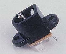
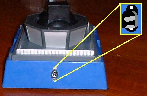
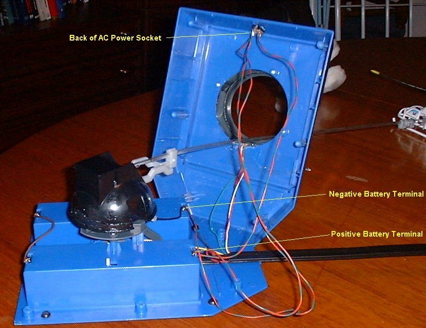
5. Following the above diagram showing the rear
connections of the AC Socket, disconnect Positive (Usually red) battery lead from the
battery compartment. This lead must be lengthened in order to stretch round to the AC
socket. Solder extra length of wire to end of positive lead and wrap connection in
insulation tape. Connect other end of lead to Terminal 1 of jack socket
The above arrangement disconnects the batteries (if fitted) when the power supply plug is pushed into the jack socket. This is in no way meant to be detrimental to the work already accomplished by other C.C. users Whilst other instructions are probably not going to kill anyone it should be remembered that is not a good idea for an external power supply to be wired directly across an internal battery pack. Placing external power in parallel with dry cell batteries, however flat they may be is a potentially dangerous situation. Unfortunately my images show that I used the same colour wire for ALL my connections. This was all I had in the house at the time plus I knew what I was doing. It’s still a bit naughty and when I get the time I’ll replace with the correct colour wires. I have subsequently made the same mods for two of my friends and used the correct colour wire for each connection. Once the wires have been soldered in place they can be routed round the side of the battery compartment to make things nice and neat before replacing the cover and screwing it shut. OverheatingHaving made my conversion and using a 6V 1200ma power supply for half an hour or so I noticed that part of the landing pad was getting hot. This seemed strange. The only components near there were for the sound effects and I had these switched off. I opened the access panel for the sound effects and found a small regulator . Whilst this had a small heat sink on it, it was not dissipating the heat fast enough.Switching the Mains adapter down to the 4.5 V setting seemed to run the regulator at a cooler temperature without compromising the performance of the helicopter. Failing that a piece of aluminium could be fitted to the top of the regulator to increase the surface area of the existing heat sink allowing the heat to dissipate quicker. This could be scavenged from the lid of an old tin can and cut to shape with vents in it. Gaudy but effective!!!!!! I guess that when a new set of D cells are put into a Chopper Command and it is switched on it is probably only pulling 6V for a short amount of time after that the battery power will fade off slowly until the battery becomes flat, making the average current over the life of a set batteries about 4 or 5 volts. Disclaimer
|
|||||||||